Now was high time for real testing: a 2 days tour covering more than 200 km and carrying all gear for independent camping.
By train to Strasbourg, the capital city of Alsace. Here is the bike, named Virginia, just outside the train station.
Fully loaded: 2 Ortlieb panniers, the tent, a 25 liter backpack for the day and the toolbag.
The cathedral in Strasbourg. Look below right, I have already my first customer. The bike called attention everywhere.
People were very curious about this bike. They asked questions, congratulated me and were delighted. The hammock seat proved irresistible.
From Strasbourg to Molsheim and then south along the Route des Vins. In the picture below in the main square at Obernai.
Camping at Ribeauville, after good 100 km.
Hunawihr
Riquewihr
Then Kaysersberg, Colmar, Neuf Brisach and Mulhouse. Another good 110 km for the second day.
A Portrait of the Artist as a Young Man
Badenia Cycles
Hand-made bicycle concepts out of recycled materials
Evolution
Thursday, June 16, 2011
Saturday, April 9, 2011
Improvements and adjustments
I first noticed the crack in the front fixation point due to the effect on frame lateral stiffness during the way back home in the maiden trip. It was rather demoralizing, after so much work put into this project, so I let the bike sit for a couple of weeks before I came up with a new set of ideas.
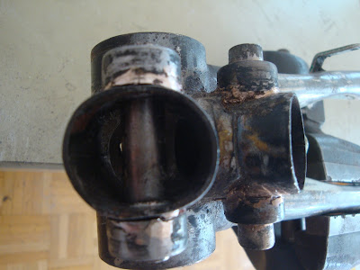
Finally, I took apart the fixation and proceeded with the root cause analysis of the failure. My fixation design was flawed, as the lateral compression stresses cannot be taken by the short stem from the original down tube of the donor bicycle. I totally underestimated the level of those localized stresses. In the next two pictures the extent and mechanism of the damage can be seen.
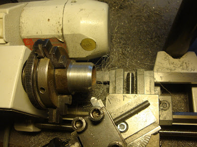
The plan was to reinforce the tube with an inner plug. The same plug is to be used as a tool to stretch the cross section of the tube back to round. Below you can see the plug being turned in the Unimat out of a massive steel bar from an old spark plug tool. A conical shape was machined in the tip to open up the deformed tube cross section.
Fitting the plug into the tube.
Cross section back to perfect round shape. At this point, as I noticed that it was not very difficult to bring the tube back to shape again, I realized that the reinforcement should have been planned in the first place.
Even if it did not fail yet, I decided to apply a similar reinforcement to the rear fixation support. The only difference is that for the front plug I will drill again the hole for the transversal tube; for the rear fixation I carved a notch in the plug in order to mount it without ondoing the brazings in the fixation that did not fail.
Additionally, I decided to apply a set of lateral brackets to further reinforce the front fixation point. I started with a rectangular piece of a 1.5 mm steel plate and shaped the curve around a tube with the same diameter as the donor bike's down tube.
A little bending here and there, fluxed... and ready to braze.
Here is the final result. It might not look very delicate, but solid it is.
And after a couple hundred kilometers, it is still in perfect condition.
Saturday, April 2, 2011
Maiden trip
Finally, on a sunny Saturday in April I took the bike for a test ride. The work is far from being finished, but a ride at this point was necessary, with the following goals
- to test the riding stability and steering geometry,
- to test the riding position for ergonomics and confort
- to check the strenght of the different components,
- to discover weak points and derive ideas for modifications
- to discover potential for improvement in my recreation of the Pedersen concept
I recognize that these goals are too ambitious for a first ride. The testing phase will be extended during some time, probably the first 500 km or so, before I can finalize the details, install all the accessories and then disassemble for painting.
Here are a couple of pictures of the bike at the moment of the test ride. No details yet at all: no rear mudguard, no chainguard, the gear shifter just tied to the seat belt, etc. However, the bike is perfectly functional with 5 speed gear internal hub with backpedal coaster brake and front caliper brake. I took my legendary green triangle tool-bag with me, just in case.
Here is a video of my shade, to get a more dynamic impression.
The maiden trip and test ride covered a 50km roundtrip from home and back, without major incidents.
Some conclusions of in the following
Steering geometry and stability
Riding stability proved very satisfactory. The bike was really stable and fun to ride. Several times riding downhill I surpassed 30-35 km/h with a very stable handling. In spite of the shallow rake angle of 66 deg, the trail I designed for the steering geometry proved right.
Ergonomics and confort
Pedalling position is very confortable. The archetypical riding position of leaning over the handlebars changes with the Pedersen concept towards a straight and confortable upright back position. This position, of course, is suitable for confortable cruising, but is less suitable for unleashing bursts of pedalling power while climbing hills or accelerating the vessel. Standing on the pedals is not possible, as the seat and handlebars are positioned rather to the rear, compared with a standard bicycle. The handlebars in this particular bike proved to be rather low and this needs to be corrected. Also the angle setting of the handlebars needs improvement for added confort on the wrist position.
Weak points
The front fixation point suffered due to deformation of the tube out of round. As can be seen in the pictures below, the very high lateral localized stresses introduced by the tubes connected to the head tube and to the fork bracket did deform the cross section of the tube and cracked the brazing joint in one side. The crack happened after about 20 km. At the beginning the problem was barely noticeable, and then it was increasing towards the end of the trip as lateral rigidity of the frame was being affected along with further deformation of the tube. In the picture you can see the final condition after 50 km. However, the bike came back home in one piece.
The rear fixation point did not suffer any cracks. The main difference being that it was subjected to steady loading from the saddle support beams, instead of the alternating loading left and right transmitted by the fork support to the front fixation and derived from the pedalling action.
Saturday, March 12, 2011
Reinforcing the fixation points
After some testing of the frame once assembled, it was clear that the front fixation point over the pedal bracket, connecting the beams to the head tube and to the fork bracket was not strong enough. The front support is subjected to large stresses as it supports all the loading from the fork. Moreover, while pedaling there are alternating stresses left and right. The brazing joint I made was not strong enough for taking these localized stresses. The reason was that both cylinders, the down tube of the original frame and the 10mm tube, intersect each other over a very small area. On the other hand, the key to sound brazing joints are large areas of contact with a very small and controlled gap. With the current design, those factors were not secured; therefore, I needed to device a solution to increase the area of contact of the different components of the whole assembly.
I started by turning some reinforcing rings to be brazed to the cantilevered tube at each side, which in turn offer a generous lateral contact surface to the main tube of the frame. You can see below the boring of the internal hole to 10 mm. The internal diameter is important for the gap design to the inner tube for brazing. A gap of about 0.3mm is satisfactory.
Here is how the concept looked in the front fixation point. So far, so good. Detailed mitering of the lateral contact surface is not yet done.
All four reinforcing rings machined and ready.
The rear support reinforcement rings are brazed without major problem. I left the front support to the end, as it is the most loaded and critical, and I could benefit from the experience of brazing the rear support first.
Front support done.
Saturday, February 26, 2011
Gears
The donor bicycle had a Sachs Huret Commander hybrid derailleur and internal hub gear with 12 speeds (6x2). Note the bent rear rim, by the way.
The origins of this derailleur goes back to 1980, when Fichtel and Sachs bought the French bicycle component manufacturer Huret. They combined the 2-speed internal gear hub "Orbit" by Sachs with a Huret derailleur in versions of 5x2, 6x2 and 7x2.
This type of gear was popular during the 80s, specially for street bicycles with 28" wheels for urban transport. It was sold with the Sachs-Commander lever system for control, with two levers placed at hand in the handlebar, one controlling the internal gear hub and the other the derrailleur. The levers had defined steps with notches to engage, what was not common in the 80s, as friction levers was the usual. The very straightforward shifting and the reliable operation of this gear system contributed to the popularity among the general public of non-specialized cyclists.
Those of you willing to learn more about the history and technical features of this bicycle gear, are referred to the following sites:
http://www.disraeligears.co.uk/Site/Sachs-Huret_Commander_derailleur_-_instructions.html
http://www.karstilo.net/hpv/technik/sachs_sram/2gang/index.php
At the beginning I planned to recycle the Sachs-Huret Commander, as it fitted the requirements of this bike. I disassembled the wheel and took the internal hub apart. Luckily I found in the web the assembly schematics and the manuals. In the following pictures the disassembled hub can be seen.
It has 2 gears: High, or direct transmission through the engaging of the pawls in the central axis assembly with the ratchet mounted in the aluminium casing; and low gear with a ratio of 0,74:1 via 3 planetary gears and the sun gear machined in the central shaft.
I cleaned, greased and put the hub back together. It was in good working condition. On the other hand, I cleaned and oiled the derailleur and control levers.
However, one day I was talking to a colleage at work who is also interested in bicycle projects and he offered me a Sachs Pentasport 5 gear internal hub, as he had one in his cellar since long with no prospects of ever using it in his projects. Thanks, André!
At first you might think that this was not a good idea, as I would decrease the functionality from 12 speeds of the Sachs-Huret to only 5 speeds of the Pentasport. This, however, is not correct. The Sachs-Huret, was created by merging 2 existing products into one. The final result, was a gear system reliable and easy to operate in street bikes, but the spacing of the gears is not optimized, as the high and low ranges are largely superimposed. This means that not all 12 gears are of practical use, as many combinations are redundant. Morever, the most important feature is the range from maximum to minimum transmission ratio.
In the following table I compared three scenarios: Sachs-Huret Commander 6x2, Sachs Pentasport and a Sturmey Archer AW 3-speed (I have many of these around in my cellar).
You see that the Sachs Pentasport, with a more compact and modern design, covers the same range of transmission ratio from 3,3m to 7,5m per pedal revolution with only 5 speeds, commanded by a single trigger-type lever. The Sachs Huret has superimposed ratios in the ranges L4-L6 and H1-H4, so that there are only 8 meaningful transmission ratios that can be achieved. On top of that, the lower ratios L1-L4 are grouped very tight together, making some of them redundant. The Sturmey-Archer, on the other hand, could be confortably used only in gentle slopes as the lower ratio starts from 4m per pedal revolution. I expect this bicycle to climb slopes up to 8%. Then, the Pentasport is the best of the three options.
Here it is, the Pentasport internal gear hub, duriing the process of frame development after the design-as-you-go methodology.
The origins of this derailleur goes back to 1980, when Fichtel and Sachs bought the French bicycle component manufacturer Huret. They combined the 2-speed internal gear hub "Orbit" by Sachs with a Huret derailleur in versions of 5x2, 6x2 and 7x2.
This type of gear was popular during the 80s, specially for street bicycles with 28" wheels for urban transport. It was sold with the Sachs-Commander lever system for control, with two levers placed at hand in the handlebar, one controlling the internal gear hub and the other the derrailleur. The levers had defined steps with notches to engage, what was not common in the 80s, as friction levers was the usual. The very straightforward shifting and the reliable operation of this gear system contributed to the popularity among the general public of non-specialized cyclists.
Those of you willing to learn more about the history and technical features of this bicycle gear, are referred to the following sites:
http://www.disraeligears.co.uk/Site/Sachs-Huret_Commander_derailleur_-_instructions.html
http://www.karstilo.net/hpv/technik/sachs_sram/2gang/index.php
At the beginning I planned to recycle the Sachs-Huret Commander, as it fitted the requirements of this bike. I disassembled the wheel and took the internal hub apart. Luckily I found in the web the assembly schematics and the manuals. In the following pictures the disassembled hub can be seen.
It has 2 gears: High, or direct transmission through the engaging of the pawls in the central axis assembly with the ratchet mounted in the aluminium casing; and low gear with a ratio of 0,74:1 via 3 planetary gears and the sun gear machined in the central shaft.
I cleaned, greased and put the hub back together. It was in good working condition. On the other hand, I cleaned and oiled the derailleur and control levers.
However, one day I was talking to a colleage at work who is also interested in bicycle projects and he offered me a Sachs Pentasport 5 gear internal hub, as he had one in his cellar since long with no prospects of ever using it in his projects. Thanks, André!
At first you might think that this was not a good idea, as I would decrease the functionality from 12 speeds of the Sachs-Huret to only 5 speeds of the Pentasport. This, however, is not correct. The Sachs-Huret, was created by merging 2 existing products into one. The final result, was a gear system reliable and easy to operate in street bikes, but the spacing of the gears is not optimized, as the high and low ranges are largely superimposed. This means that not all 12 gears are of practical use, as many combinations are redundant. Morever, the most important feature is the range from maximum to minimum transmission ratio.
In the following table I compared three scenarios: Sachs-Huret Commander 6x2, Sachs Pentasport and a Sturmey Archer AW 3-speed (I have many of these around in my cellar).
You see that the Sachs Pentasport, with a more compact and modern design, covers the same range of transmission ratio from 3,3m to 7,5m per pedal revolution with only 5 speeds, commanded by a single trigger-type lever. The Sachs Huret has superimposed ratios in the ranges L4-L6 and H1-H4, so that there are only 8 meaningful transmission ratios that can be achieved. On top of that, the lower ratios L1-L4 are grouped very tight together, making some of them redundant. The Sturmey-Archer, on the other hand, could be confortably used only in gentle slopes as the lower ratio starts from 4m per pedal revolution. I expect this bicycle to climb slopes up to 8%. Then, the Pentasport is the best of the three options.
Here it is, the Pentasport internal gear hub, duriing the process of frame development after the design-as-you-go methodology.
Friday, February 18, 2011
Seat - Shaking the paradigm of equestrian saddles
The hammock seat constitutes the very essence of the Pedersen concept. This hammock saddle suspended from springs and belts to the rest of the frame structure eradicates forever that imaginary horse the cyclist is seating astride, thus shattering the paradigm derived from centuries of equestrian tradition. This configuration is very adaptable to the cyclist's anatomy and allows for lateral oscillations and tilting while pedaling or leaning sidewards.
The original Dursley Pedersen had a woven seat as seen below
At the beginning of the project I was considering weaving my own seat. In the following site there are very detailed instructions.
http://www.dursley-pedersen.net/weave.html
However, I finally decided on a more conventional and pragmatic solution, based on an old Brooks leather saddle.
I found an old and neglected Brooks B66, as you see in the picture below. Very classic and aristocratic looks. I can recycle it and with some rejuvenation to the leather part, it will fit perfectly the style of this bike.
The lower support structure and springs were disassembled. I kept, of course, the internal structure that stretches the leather part between the rear and front copper rivets. This structure and not the leather will be taking the stresses introduced by the anchoring points.
In order to fix the front to the head tube by means of a leather belt I need to manufacture a kind of bracket to hold the shackle. I used a 1.5 mm metal plate, that can be seen below.
Cutting, drilling, filing... All by hand. No power tools.
Bending a nice curl with the diameter for the shackle eye-bolt. I brazed the joint at the curl.
Here it is, assembled to the seat leather tensioning mechanism.
Note the internal seat structure and the springs attached to the rear part.
Another view of the seat assembly ready for mounting.
To attach the front shackle to the rest of the frame I am using a pair of old Swiss military belts from the 50s-60s. If they were originally used in backpacks or horses I can not say. But they are made out of very strong and seasoned leather and have the classic looks that fit with the style of this bike.
First view of how the bicycle looks like at the moment. It is not yet finished, not yet even ridable. However, it is taking shape. To connect the seat stays to the rear dropouts I used 3.5 mm steel cable passing through the tube at the extreme of the trombone's upper adjustable part. The positioning of the handlebars is not realistic. In such a position there would be interference with the knees and unconfortable wrist position. I just mounted all parts together for the first picture.
Subscribe to:
Posts (Atom)