Evolution

Evolution

Saturday, January 22, 2011

Frame parts - the trombone

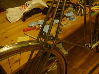
In the previous blog entry I showed some pictures of the frame taking shape. However, the seat stays were still missing. I call seat stays the tube structure that is fixed to the rear fixation point over the pedal bracket, which supports the rear anchoring point of the seat. This tube structure, has to be extensible to accomodate different cyclist sizes, within reason.

I opted for a parallel tubing setup. Most Pedersen designs I have seen, the original Dursley Pedersen, or those from Jesper Solling or from Kemper, use in general an angle in the seat tubes, for one reason or the other.

See the following Dursley Pedersen, for example, and how the seat tubes form an angle.


For my frame I wanted a parallel tubing construction, as it gives me much more freedom for the seat height adjusting mechanism. The lower part is made of two pieces of 12mm tubing, with two traverse tubes to reinforce. Shown here just after brazing.


The upper adjustable part of the structure is made out of 10mm stainless steel tubing. Ideally, they should fit into the 12mm tubing of the lower part. This, however, proved not true, and I had to find a way to decrease slightly the diameter of the inner tubing to get a proper fit.

This was not to be an easy task, as we are dealing with very slender and long (about 40 cm) tubes of inox steel. Finally, I came up with the following solution. I took a Pultra 10mm watchmaker's lathe that you see below. Added an extra D-shaped bed and a cross slide from a Lorch-Schmidt 6mm lathe, to produce an extra-long lathe for the purpose. Since I do not have a self-centering chuck for the Pultra 10, I used a chuck with adjusting bolts. That is why you see a dial indicator in the picture for centering the workpiece.


Not that I specially recommend this setup, but it worked for me, lacking a better solution.


Mitering the tubes for brazing.


Preassembly to braze in place the upper part of the trombone. Parallelism is the key.


Perfect parallelism and easy sliding action achieved.


Next, the securing bolts to adjust to desired length.

Saturday, January 15, 2011

Frame tubes

For the frame parts I used regular steel tubing 12mm diameter with 1mm wall thickness. As mentioned before, my frame is designed as a bolted construction. Therefore, I had to develop a method for manufacturing the fixation points at the tip of the tubes in a standardized and simple manner, and yet strong enough for the function.

I came up with the following process. First, I gently pressed the tip of the tube in the vice as seen in the picture below. In steps, applying pressure at different points and shaping slowly in a constant tapered shape without buckling or collapsing the tube at any point.


Then I filed two washers to an angular shape as seen below, in such a way that the angle matches the taper in the tubing.


Next I hammered tightly both washers into the tubing crevice.


In the picture below, results can be seen after thorough brazing.


...and final results after drilling and filing.


Here is, for example, the frame part the connects the rear dropouts with the head tube.


In a similar fashion I crafted the beams that connect the pedal bracket front fixation point with the lower connecting point of the fork. As mentioned in an earlier post, the fork lower bracket is provided with an articulated joint that is to be fixed to these beams. I am showing below how did I manufacture the support at the tip to the lower fork beams which is to be assembled to the articulated joint.

Starting from a metal plate 2 mm thick, I bent it in the vice using a 12 mm tube to define the bending radius.


Here it is, nicely bent, with parallel wings. The rest is just standard cutting, filing and driling.


Brazing the support in place needed some creativity to hold the assembly in the correct position during the process.


The frame is taking shape, after all. Disregard the mess in my working table. I was just too eager to see the frame preliminarily assembled.


Mounting the fork, just to get the feeling of how the complete beast might look like.


Starting to look like a bike after all...

Saturday, January 8, 2011

Frame fittings

For the frame of my Pedersen I planned a bolted construction recycling the bottom bracket with chain stays of the donor bike. By recycling this module I can rely on the rigidity and correct alignment of the original donor bicycle dropouts without, literally, reinventing the wheel. The bolted feature is an old idea of mine which might be questioned by many fellow Pedersen builder enthusiasts: why to compromise the resistance and rigidity of a solidly throughout brazed frame, by including some bolted joints?

A few points on my behalf in the following:

The Pedersen frame concept relies in a truss construction. A truss construction by definition consists in individual elements jointed at nodes. These elements are subjected either to tensile or compressive stresses, but no flexural moments are taken by the elements, as the rotational degree of freedom in the nodes is not restricted. The fact that the nodes take no bending efforts, makes the resolution of the structural system relatively simple, as all loads are applied to the nodes and all elements are just subjected to tensile-compressive stresses without complex stresses as shear, bending and torsion.

Therefore, solidly brazing at a certain node the different elements in a specific position , would go completely against the very essence of a truss construction. The nodal equations for bending moments would be no longer zero and this would render useless the standard calculation procedure to resolve such a truss structural system.

A caveat, though: this specific truss structure of the Pedersen frame is statically indeterminate. For a truss system to be statically determinate, there is a certain relationship between number of members, nodes and degrees of freedom in the fixation restrains of the structure, which must be kept. When there are excess of members to the minimum necessary, so to speak, the system can not be resolved by the sole application of Newton's equations of mechanical equilibrium. In such cases more involved resolution methods are necessary.

In this case, even if I fully trust old Mikael Pedersen, I used the demo version of the following software

http://www.masoftware.se/index.html

It is a very effective software for truss calculation with a user-friendly interface. My temporary license expired and I did not do any screenshots, so you might have to believe me that the stresses and deflections in my frame are acceptable.

The following picture, illustrates very well the tensional stresses taken by the gentlemen's arms and the compressive stresses taken by the bars fixed to the chairs.


Another point to justify the bolted construction is that I wanted a modular type of bicycle that can be dissassembled for travelling, say by train or by plane, taking the space of a normal piece of luggage. The modular concept would allow for future changes in the frame: different fork, alteration of members for different frame geometry, or even expanding the concept to a tandem.

After all this preliminary digression, back to the workshop...

Here is the bracket and chain stays assembly from the donor bike. My intention now is to fabricate in this part the fixation points to attach this module to the rest of my frame.
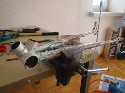


As a first step I drilled a hole through the base of the original seat tube. Care has to be taken that it is perfectly perpendicular to the longitudinal axis.


Careful filing to fit a 10mm tube with 1mm wall thickness.


Here is how it looks like immediately after brazing both tubes in place. You might have observed that the front tube is shorter than the rear. The reason is that in the front joint both the beams connected to the head tube and to the fork bracket are to be fixed. On the other hand, in the rear tube only the seat stays will be fixed.


The next step was to fabricate the fixation points at the rear dropouts, to fix the frame members that connect with the head tube. The parts were turned in the lathe, drilled and filed, as you see in the next picture.


This is how the fixation points look brazed in place.