Evolution

Evolution

Saturday, March 12, 2011

Reinforcing the fixation points

After some testing of the frame once assembled, it was clear that the front fixation point over the pedal bracket, connecting the beams to the head tube and to the fork bracket was not strong enough. The front support is subjected to large stresses as it supports all the loading from the fork. Moreover, while pedaling there are alternating stresses left and right. The brazing joint I made was not strong enough for taking these localized stresses. The reason was that both cylinders, the down tube of the original frame and the 10mm tube, intersect each other over a very small area. On the other hand, the key to sound brazing joints are large areas of contact with a very small and controlled gap. With the current design, those factors were not secured; therefore, I needed to device a solution to increase the area of contact of the different components of the whole assembly.


I started by turning some reinforcing rings to be brazed to the cantilevered tube at each side, which in turn offer a generous lateral contact surface to the main tube of the frame. You can see below the boring of the internal hole to 10 mm. The internal diameter is important for the gap design to the inner tube for brazing. A gap of about 0.3mm is satisfactory.


Here is how the concept looked in the front fixation point. So far, so good. Detailed mitering of the lateral contact surface is not yet done.


All four reinforcing rings machined and ready.


The rear support reinforcement rings are brazed without major problem. I left the front support to the end, as it is the most loaded and critical, and I could benefit from the experience of brazing the rear support first.


Front support done.

Saturday, February 26, 2011

Gears

The donor bicycle had a Sachs Huret Commander hybrid derailleur and internal hub gear with 12 speeds (6x2). Note the bent rear rim, by the way.


The origins of this derailleur goes back to 1980, when Fichtel and Sachs bought the French bicycle component manufacturer Huret. They combined the 2-speed internal gear hub "Orbit" by Sachs with a Huret derailleur in versions of 5x2, 6x2 and 7x2.


This type of gear was popular during the 80s, specially for street bicycles with 28" wheels for urban transport. It was sold with the Sachs-Commander lever system for control, with two levers placed at hand in the handlebar, one controlling the internal gear hub and the other the derrailleur. The levers had defined steps with notches to engage, what was not common in the 80s, as friction levers was the usual. The very straightforward shifting and the reliable operation of this gear system contributed to the popularity among the general public of non-specialized cyclists.


Those of you willing to learn more about the history and technical features of this bicycle gear, are referred to the following sites:

http://www.disraeligears.co.uk/Site/Sachs-Huret_Commander_derailleur_-_instructions.html

http://www.karstilo.net/hpv/technik/sachs_sram/2gang/index.php

At the beginning I planned to recycle the Sachs-Huret Commander, as it fitted the requirements of this bike. I disassembled the wheel and took the internal hub apart. Luckily I found in the web the assembly schematics and the manuals. In the following pictures the disassembled hub can be seen.


It has 2 gears: High, or direct transmission through the engaging of the pawls in the central axis assembly with the ratchet mounted in the aluminium casing; and low gear with a ratio of 0,74:1 via 3 planetary gears and the sun gear machined in the central shaft.


I cleaned, greased and put the hub back together. It was in good working condition. On the other hand, I cleaned and oiled the derailleur and control levers.

However, one day I was talking to a colleage at work who is also interested in bicycle projects and he offered me a Sachs Pentasport 5 gear internal hub, as he had one in his cellar since long with no prospects of ever using it in his projects. Thanks, André!

At first you might think that this was not a good idea, as I would decrease the functionality from 12 speeds of the Sachs-Huret to only 5 speeds of the Pentasport. This, however, is not correct. The Sachs-Huret, was created by merging 2 existing products into one. The final result, was a gear system reliable and easy to operate in street bikes, but the spacing of the gears is not optimized, as the high and low ranges are largely superimposed. This means that not all 12 gears are of practical use, as many combinations are redundant. Morever, the most important feature is the range from maximum to minimum transmission ratio.

In the following table I compared three scenarios: Sachs-Huret Commander 6x2, Sachs Pentasport and a Sturmey Archer AW 3-speed (I have many of these around in my cellar).


You see that the Sachs Pentasport, with a more compact and modern design, covers the same range of transmission ratio from 3,3m to 7,5m per pedal revolution with only 5 speeds, commanded by a single trigger-type lever. The Sachs Huret has superimposed ratios in the ranges L4-L6 and H1-H4, so that there are only 8 meaningful transmission ratios that can be achieved. On top of that, the lower ratios L1-L4 are grouped very tight together, making some of them redundant. The Sturmey-Archer, on the other hand, could be confortably used only in gentle slopes as the lower ratio starts from 4m per pedal revolution. I expect this bicycle to climb slopes up to 8%. Then, the Pentasport is the best of the three options.


Here it is, the Pentasport internal gear hub, duriing the process of frame development after the design-as-you-go methodology.


Friday, February 18, 2011

Seat - Shaking the paradigm of equestrian saddles

The hammock seat constitutes the very essence of the Pedersen concept. This hammock saddle suspended from springs and belts to the rest of the frame structure eradicates forever that imaginary horse the cyclist is seating astride, thus shattering the paradigm derived from centuries of equestrian tradition. This configuration is very adaptable to the cyclist's anatomy and allows for lateral oscillations and tilting while pedaling or leaning sidewards.

The original Dursley Pedersen had a woven seat as seen below

At the beginning of the project I was considering weaving my own seat. In the following site there are very detailed instructions.

http://www.dursley-pedersen.net/weave.html

However, I finally decided on a more conventional and pragmatic solution, based on an old Brooks leather saddle.


I found an old and neglected Brooks B66, as you see in the picture below. Very classic and aristocratic looks. I can recycle it and with some rejuvenation to the leather part, it will fit perfectly the style of this bike.


The lower support structure and springs were disassembled. I kept, of course, the internal structure that stretches the leather part between the rear and front copper rivets. This structure and not the leather will be taking the stresses introduced by the anchoring points.


In order to fix the front to the head tube by means of a leather belt I need to manufacture a kind of bracket to hold the shackle. I used a 1.5 mm metal plate, that can be seen below.


Cutting, drilling, filing... All by hand. No power tools.


Bending a nice curl with the diameter for the shackle eye-bolt. I brazed the joint at the curl.


Here it is, assembled to the seat leather tensioning mechanism.


Note the internal seat structure and the springs attached to the rear part.


Another view of the seat assembly ready for mounting.


To attach the front shackle to the rest of the frame I am using a pair of old Swiss military belts from the 50s-60s. If they were originally used in backpacks or horses I can not say. But they are made out of very strong and seasoned leather and have the classic looks that fit with the style of this bike.
First view of how the bicycle looks like at the moment. It is not yet finished, not yet even ridable. However, it is taking shape. To connect the seat stays to the rear dropouts I used 3.5 mm steel cable passing through the tube at the extreme of the trombone's upper adjustable part. The positioning of the handlebars is not realistic. In such a position there would be interference with the knees and unconfortable wrist position. I just mounted all parts together for the first picture.

Saturday, January 22, 2011

Frame parts - the trombone

In the previous blog entry I showed some pictures of the frame taking shape. However, the seat stays were still missing. I call seat stays the tube structure that is fixed to the rear fixation point over the pedal bracket, which supports the rear anchoring point of the seat. This tube structure, has to be extensible to accomodate different cyclist sizes, within reason.

I opted for a parallel tubing setup. Most Pedersen designs I have seen, the original Dursley Pedersen, or those from Jesper Solling or from Kemper, use in general an angle in the seat tubes, for one reason or the other.

See the following Dursley Pedersen, for example, and how the seat tubes form an angle.


For my frame I wanted a parallel tubing construction, as it gives me much more freedom for the seat height adjusting mechanism. The lower part is made of two pieces of 12mm tubing, with two traverse tubes to reinforce. Shown here just after brazing.


The upper adjustable part of the structure is made out of 10mm stainless steel tubing. Ideally, they should fit into the 12mm tubing of the lower part. This, however, proved not true, and I had to find a way to decrease slightly the diameter of the inner tubing to get a proper fit.

This was not to be an easy task, as we are dealing with very slender and long (about 40 cm) tubes of inox steel. Finally, I came up with the following solution. I took a Pultra 10mm watchmaker's lathe that you see below. Added an extra D-shaped bed and a cross slide from a Lorch-Schmidt 6mm lathe, to produce an extra-long lathe for the purpose. Since I do not have a self-centering chuck for the Pultra 10, I used a chuck with adjusting bolts. That is why you see a dial indicator in the picture for centering the workpiece.


Not that I specially recommend this setup, but it worked for me, lacking a better solution.


Mitering the tubes for brazing.


Preassembly to braze in place the upper part of the trombone. Parallelism is the key.


Perfect parallelism and easy sliding action achieved.


Next, the securing bolts to adjust to desired length.

Saturday, January 15, 2011

Frame tubes

For the frame parts I used regular steel tubing 12mm diameter with 1mm wall thickness. As mentioned before, my frame is designed as a bolted construction. Therefore, I had to develop a method for manufacturing the fixation points at the tip of the tubes in a standardized and simple manner, and yet strong enough for the function.

I came up with the following process. First, I gently pressed the tip of the tube in the vice as seen in the picture below. In steps, applying pressure at different points and shaping slowly in a constant tapered shape without buckling or collapsing the tube at any point.


Then I filed two washers to an angular shape as seen below, in such a way that the angle matches the taper in the tubing.


Next I hammered tightly both washers into the tubing crevice.


In the picture below, results can be seen after thorough brazing.


...and final results after drilling and filing.


Here is, for example, the frame part the connects the rear dropouts with the head tube.


In a similar fashion I crafted the beams that connect the pedal bracket front fixation point with the lower connecting point of the fork. As mentioned in an earlier post, the fork lower bracket is provided with an articulated joint that is to be fixed to these beams. I am showing below how did I manufacture the support at the tip to the lower fork beams which is to be assembled to the articulated joint.

Starting from a metal plate 2 mm thick, I bent it in the vice using a 12 mm tube to define the bending radius.


Here it is, nicely bent, with parallel wings. The rest is just standard cutting, filing and driling.


Brazing the support in place needed some creativity to hold the assembly in the correct position during the process.


The frame is taking shape, after all. Disregard the mess in my working table. I was just too eager to see the frame preliminarily assembled.


Mounting the fork, just to get the feeling of how the complete beast might look like.


Starting to look like a bike after all...

Saturday, January 8, 2011

Frame fittings

For the frame of my Pedersen I planned a bolted construction recycling the bottom bracket with chain stays of the donor bike. By recycling this module I can rely on the rigidity and correct alignment of the original donor bicycle dropouts without, literally, reinventing the wheel. The bolted feature is an old idea of mine which might be questioned by many fellow Pedersen builder enthusiasts: why to compromise the resistance and rigidity of a solidly throughout brazed frame, by including some bolted joints?

A few points on my behalf in the following:

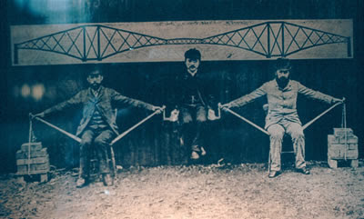
The Pedersen frame concept relies in a truss construction. A truss construction by definition consists in individual elements jointed at nodes. These elements are subjected either to tensile or compressive stresses, but no flexural moments are taken by the elements, as the rotational degree of freedom in the nodes is not restricted. The fact that the nodes take no bending efforts, makes the resolution of the structural system relatively simple, as all loads are applied to the nodes and all elements are just subjected to tensile-compressive stresses without complex stresses as shear, bending and torsion.

Therefore, solidly brazing at a certain node the different elements in a specific position , would go completely against the very essence of a truss construction. The nodal equations for bending moments would be no longer zero and this would render useless the standard calculation procedure to resolve such a truss structural system.

A caveat, though: this specific truss structure of the Pedersen frame is statically indeterminate. For a truss system to be statically determinate, there is a certain relationship between number of members, nodes and degrees of freedom in the fixation restrains of the structure, which must be kept. When there are excess of members to the minimum necessary, so to speak, the system can not be resolved by the sole application of Newton's equations of mechanical equilibrium. In such cases more involved resolution methods are necessary.

In this case, even if I fully trust old Mikael Pedersen, I used the demo version of the following software

http://www.masoftware.se/index.html

It is a very effective software for truss calculation with a user-friendly interface. My temporary license expired and I did not do any screenshots, so you might have to believe me that the stresses and deflections in my frame are acceptable.

The following picture, illustrates very well the tensional stresses taken by the gentlemen's arms and the compressive stresses taken by the bars fixed to the chairs.


Another point to justify the bolted construction is that I wanted a modular type of bicycle that can be dissassembled for travelling, say by train or by plane, taking the space of a normal piece of luggage. The modular concept would allow for future changes in the frame: different fork, alteration of members for different frame geometry, or even expanding the concept to a tandem.

After all this preliminary digression, back to the workshop...

Here is the bracket and chain stays assembly from the donor bike. My intention now is to fabricate in this part the fixation points to attach this module to the rest of my frame.
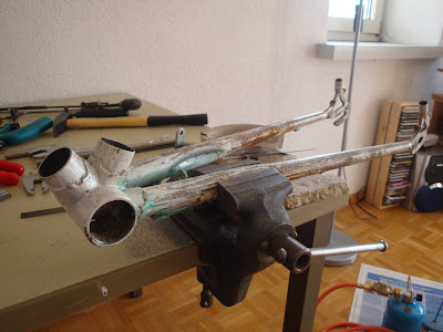


As a first step I drilled a hole through the base of the original seat tube. Care has to be taken that it is perfectly perpendicular to the longitudinal axis.


Careful filing to fit a 10mm tube with 1mm wall thickness.


Here is how it looks like immediately after brazing both tubes in place. You might have observed that the front tube is shorter than the rear. The reason is that in the front joint both the beams connected to the head tube and to the fork bracket are to be fixed. On the other hand, in the rear tube only the seat stays will be fixed.


The next step was to fabricate the fixation points at the rear dropouts, to fix the frame members that connect with the head tube. The parts were turned in the lathe, drilled and filed, as you see in the next picture.
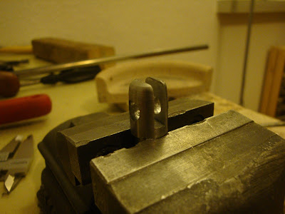


This is how the fixation points look brazed in place.